


VISSONIC_X9_series_seamless_splicing_modular_matrix_swithcer_datasheets_V3.3.pdf
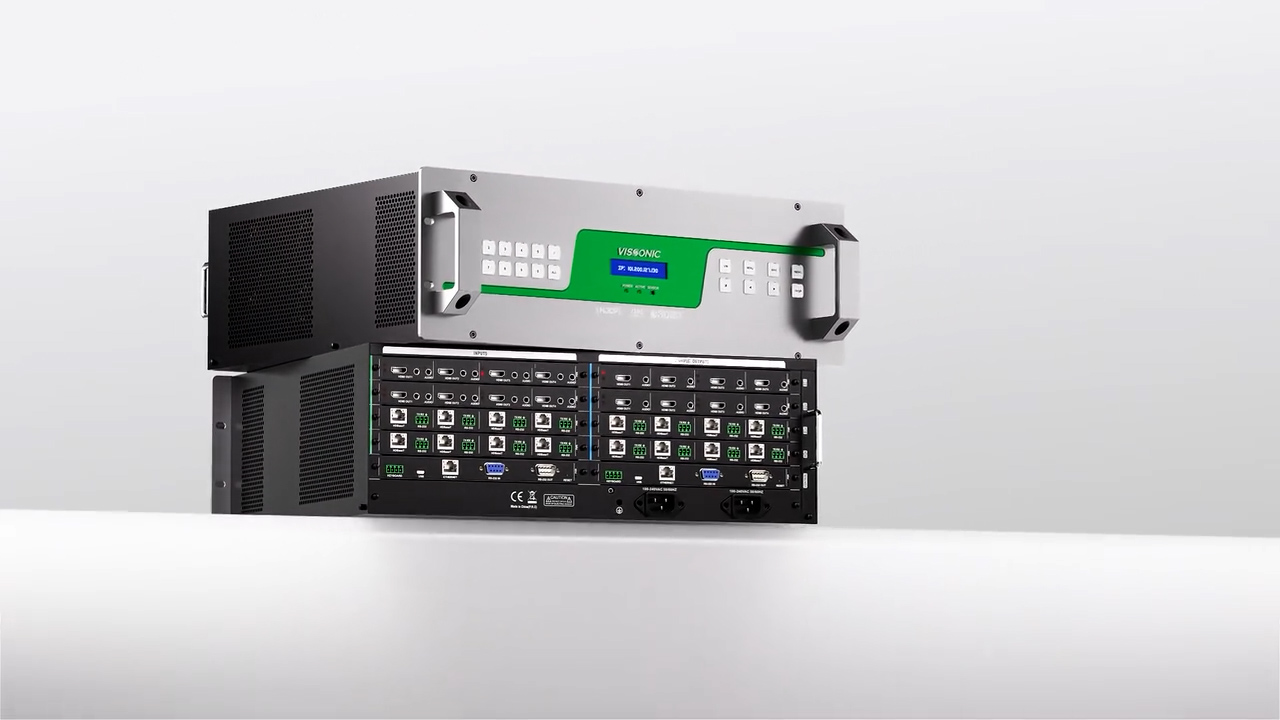
X9 Series is a LED/LCD splicing matrix switcher with modular design and plug-in structure. It supports seamless switching up to 4k@60Hz, with a wide range of up to 144x input and 144x output. It is designed for mission-critical situations that work 24/7. It has high reliability and is widely used in conference rooms, command centers, security monitoring, exhibition displays, military command, education and research, government announcements, commercial displays and other industries.
Chapter 1 Overview................................................................................................................................................. 6
1.1
Product Equipment
....................................................................................................................................
6
1.2
function
features........................................................................................................................................
7
1.3 Cabinet installation.................................................................................................................................... 7
Chapter
2 Hardware
Introductions...........................................................................................................................
9
2.1
VW-VM0808 panel diagram
.....................................................................................................................
9
2.2
VW-VM1616 panel diagram
.....................................................................................................................
9
2.3
VW-VM3636 panel diagram
...................................................................................................................
10
2.4
VW-VM7272 panel diagram
...................................................................................................................
12
2.5
VW-VM144144 panel diagram
...............................................................................................................
14
2.6 Link of matrix and peripherals ................................................................................................................ 16
2.6.1
Input interface description
............................................................................................................
16
2.6.2
Output interface description
.........................................................................................................
16
2.6.3 Control board communication port and link method.................................................................... 16
2.6.4
Matrix RS-232 control interface
...................................................................................................
16
2.6.5
Link of matrix and control
computer............................................................................................
17
2.6.6
Matrix KEYBOARD interface
.....................................................................................................
17
2.6.7 Link of matrix and extended keyboard ......................................................................................... 17
2.6.8 Ethernet/PR-LINK Interface......................................................................................................... 18
2.6.8.1
Hardware linking method
..................................................................................................
18
2.6.8.2 Connection Method Description of RJ45 Ethernet Port straight-through Line and Cross-line.......................................................................................................................................
19
2.6.9
HDMI port description
.................................................................................................................
20
2.6.10
DVI port
description...................................................................................................................
20
2.6.11 DB15 interface description ......................................................................................................... 21
2.6.12 DB15 male socket transfer cable (S terminal, RCA head).......................................................... 22
2.6.12.1 DB15 male socket transfer cable definition..................................................................... 23
Chapter
3 Control Panel Operating
Instructions....................................................................................................
24
3.1
Panel
description......................................................................................................................................
24
3.2
Board
types..............................................................................................................................................
25
3.3
Input
board...............................................................................................................................................
26
3.3.1
VW-HM4I input board function
...................................................................................................
26
3.3.2
VW-HM2I input board function
...................................................................................................
27
3.3.3
VW-HD4I CAT5 input board function
.........................................................................................
27
3.3.4
VW-IP2I IP input board
function..................................................................................................
27
3.3.5
VW-SD4I input board
function.....................................................................................................
27
3.3.6
VW-VA4I input board function
....................................................................................................
27
3.3.7
VW-DV4I input board
function....................................................................................................
28
3.3.8
VW-SF4I optical fiber input board
function.................................................................................
28
3.4 Output board............................................................................................................................................ 28
3.4.1 VW-HM4O seamless output board function................................................................................. 28
3.4.2 VW-HM2O 4K seamless output board function........................................................................... 28
3.4.3 VW-HD4O CAT5 seamless output board function....................................................................... 28
3.4.4 VW-SD4O seamless output board ................................................................................................ 29
3.4.5
VW-DV4O seamless output board function
.................................................................................
29
3.4.6
VW-VA4O seamless output board
function..................................................................................
29
3.4.7 VW-SF4O optical fiber seamless output board function .............................................................. 29
3.4.8 VW-STM4 streaming media output board function ..................................................................... 29
3.4.9 VP-HM4O stitching output board function .................................................................................. 29
3.4.10
VP-HM2O stitching output board function
................................................................................
30
3.4.11 VP-HM2O-4K stitching output board function .......................................................................... 30
3.4.12
VP-DV4O stitching output board function
.................................................................................
30
3.4.13
VP-DV2O stitching output board function
.................................................................................
30
3.4.14
VP-HD4O stitching output board function
.................................................................................
30
3.4.15
VP-HD2O stitching output board function
.................................................................................
30
3.5 Preview board.......................................................................................................................................... 30
3.5.1
VW-PVW preview board
function................................................................................................
30
3.6
Control
board...........................................................................................................................................
31
3.6.1 VW-Con ETN5 advanced control board function......................................................................... 31
3.7
Specification and Parameter
....................................................................................................................
32
3.7.1
VW-HM4I and
VW-HM4O..........................................................................................................
32
3.7.2 VW-HM2I and VW-HM2O.......................................................................................................... 32
3.7.3
VW-DV4I and VW-DV4O
...........................................................................................................
33
3.7.4
VW-HD4I and VW-HD4O
...........................................................................................................
34
3.7.5
VW-VA4I and VW-VA4O
............................................................................................................
35
3.7.6 VW-SD4I and VW-SD4O............................................................................................................. 35
3.7.7
VW-SF4I and
VW-SF4O..............................................................................................................
36
3.7.8 VW-IP2I........................................................................................................................................ 36
3.7.9
VP-HM4O.....................................................................................................................................
37
3.7.10 VP-HM2O................................................................................................................................... 38
3.7.11
VP-HM2O-4K
............................................................................................................................
38
3.7.12
VP-DV4O
...................................................................................................................................
39
3.7.13
VP-DV2O
...................................................................................................................................
40
3.7.14
VP-HD4O
...................................................................................................................................
41
3.7.15
VP-HD2O
...................................................................................................................................
41
3.7.16
VW-PVW....................................................................................................................................
42
3.7.17 VW-VM0808/1616/3636/7272/144144...................................................................................... 43
3.8
Front Panel
Operation..............................................................................................................................
44
Chapter
4
Instructions............................................................................................................................................
48
4.1
X9 processor instructions
........................................................................................................................
48
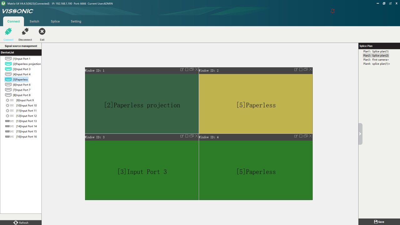
4.2
Splicer
instructions..................................................................................................................................
55